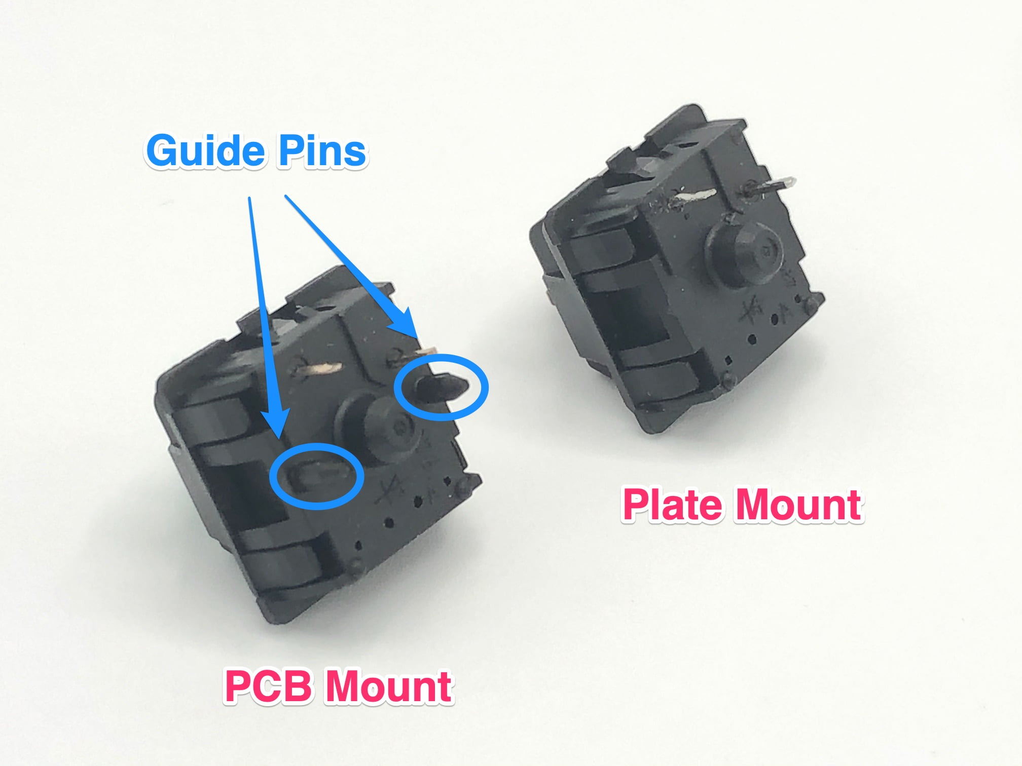
Okay, so I wanted to try out these PCB mount switches for a new keyboard project. I’d used plate mount switches before, but I heard these PCB mount ones can feel a bit more solid, so I figured, why not?
First, I grabbed the switches and my PCB. Pretty straightforward stuff. The switches have these extra plastic pins on the bottom, which are supposed to help with stability. That is the major differece with plate mount switches.
Getting Started
I started by lining up the switch with the holes on the PCB. There are five holes total: two for the LED, one big center hole for the main switch pin, and two smaller holes for those extra plastic pins. It’s kind of hard to mess this up, because the switch only fits in one way, because all pins must be match and fit the holes.
Then I pushed the switch down into the PCB. It took a little bit of force, but you hear this satisfying click when it’s in all the way. Just make sure you’re pushing straight down, so you don’t bend any of the metal pins on the switch. I did that once, total pain to fix it.
Soldering Time
Once all the switches were in place, I flipped the PCB over. Now it’s time to solder. I’m no soldering expert, but I’ve done it enough to get by.
- I heated up my soldering iron.
- Touched the solder to the pins.
- And made sure everything to get a good connection.
You just need a little bit of solder on each pin. It looks shine and smooth when solder is done. Don’t want any cold solder joints, or the switch might not work right.
The Final Result
After soldering all the switches, I tested everything out. Plugged it in, and all the keys worked perfectly! I gotta say, these PCB mount switches do feel pretty nice. A bit sturdier than the plate mount ones I’ve used, maybe, Less wobbly.

So yeah, that’s how I installed PCB mount switches. Not too hard, just takes a bit of patience and a steady hand with the soldering iron. If I can do it, you can do it. Good luck.